
Your cameras, your layout
Five camera ports and 52 TOPS on one 70 x 53 mm board. Depth and AI, wherever your robot needs eyes.
5
Camera ports52
TOPS on board70 x 53
mm carrier36 g
Barebone
Five camera ports and 52 TOPS on one 70 x 53 mm board. Depth and AI, wherever your robot needs eyes.
A custom multi-camera robot usually takes five vendors and months of glue code. Here it is one board.
Compute module and carrier
Capture card or deserializer
Cameras from another vendor
Drivers you maintain
Your own sync and calibration
RVC4, 52 TOPS on board
Five direct MIPI ports
Calibrated camera modules
DepthAI and Luxonis OS
Synced, self-calibrating
8 GB / 128 GB
2.5 GbE / PoE+
USB-C / 5 Gbps
6-32 V DC

Front, side, and rear cameras connected to one board inside your humanoid’s head.
Stereo that fits
Place the cameras to fit the head and working range.
See beyond the front
Add side and rear views, all captured in sync.
Free up the main computer
Process depth and detections on board, leaving more compute for planning and movement.

Bring onboard intelligence to your drone without a bulky companion computer.
Motion sensing built in
An onboard IMU and magnetometer provide motion and heading inputs for your flight software.
Connect to your autopilot
Exchange data over UART, CAN, or Ethernet, with 6–32 V DC power input.
Compute without the bulk
Run depth, AI, and mission logic on a 36 g barebone board.

Depth, AI, and your robot’s applications—all running on one board.
Run your applications
Use the onboard CPU and Linux environment for planning and application logic.
Process vision locally
Turn camera feeds into depth and detections without a separate host.
Connect to control
Link directly to your robot’s controllers over CAN.

From a working prototype to a product of your own.
Prototype with the kit
Get your cameras and applications working.
Build it into your product
Integrate the barebone board into your own design.
Make the hardware your own
Start your custom carrier from the open reference design.
Process depth and AI, run your robot’s applications, and connect to its controllers—all on one board.
Send depth, detections, and tracks to your robot’s main computer.
Run perception, planning, and application logic on OAK 4 FFC.
Factory-calibrated camera modules, five ports, any layout.
Stereo eyes up front, a wide view on each side, one camera behind.
Contact Us
Coming Q1 2027
Factory-calibrated modules, synchronized capture, and onboard stitching—all brought together in OAK 4 FFC.
Capture synchronized views from every camera, then combine them with a single DepthAI Stitching node.

Create a top-down surround view, projected using each camera’s calibration.

Task | Build it yourself | Build it with OAK 4 FFC |
|---|---|---|
Camera calibration | Source calibrated cameras or calibrate them, then manage their parameters | Use factory-calibrated modules with parameters stored on each module |
Rig calibration | Integrate a method to determine camera positions and orientations | Refine approximate camera positions using scene-based calibration |
Synchronized capture | Select compatible cameras and integrate their timing and triggering | Use supported camera modules with synchronized capture |
Image stitching | Choose a stitching solution and integrate it with your compute platform | Use the DepthAI Stitching node, which runs on device. |
Bandwidth | Design a pipeline to combine camera streams before sending them to a host | Send one stitched stream instead of separate raw camera feeds |
The rig self-calibrates from the surrounding scene, no targets needed.
A fixed depth camera gives you one baseline. Here you pick it: close for grippers, wide for drones.
The same compute platform and software in two configurations: a Developer Kit for prototyping and a Barebone for integration.

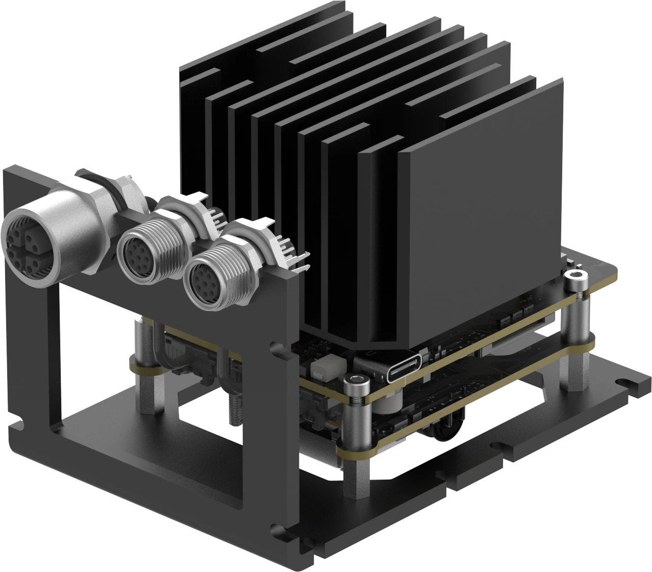
Start prototyping. Includes cooling, PoE+, connectors, and mounting hardware for development.
Carrier board with OAK 4 SoM
PoE+ module and panel-mount connector set
Passive heatsink and thermal interface material
L-bracket and mounting hardware
Camera modules sold separately.

Build it into your product. The core board for integration with your own enclosure, cooling, and connections.
Carrier board with OAK 4 SoM
Thermal interface material and mounting screws
Camera modules, connector set, PoE+ module, and cooling sold separately.
Start your custom carrier from our open reference design.
View on GitHub
Follow the setup guide and explore example applications.
Read the Docs
OAK 4 FFC uses the same software platform and development tools as other RVC4-based devices.
Planning a production run? Barebone shipments begin in Q1 2027. Talk to us about quantities, lead times, and your rollout.
Contact Sales
Compute module
OAK 4 SoM, based on RVC4
CPU and OS
6-core ARM CPU, Linux-based Luxonis OS
AI accelerator
48 TOPS INT8 / 12 TOPS FP16
GPU
4 TOPS FP16
Memory and storage
8 GB RAM, 128 GB onboard storage
Camera interface
5 × FFC connectors, 5 × MIPI CSI D-PHY, 4 lanes
Camera modules
OAK-FFC V2: IMX586, OG05, OV9282 (sold separately)
Processing
Stereo depth, filtering, RGB-depth alignment, feature tracking, neural-network inference
Calibration
Factory-calibrated module intrinsics; rig calibration with Dynamic Calibration
Ethernet
Up to 2.5 Gbps
USB-C
Up to 5 Gbps, host and device
Auxiliary I/O
Debug UART / GPIO, FSYNC / STROBE, USB 2.0 host, 5 V output
Expansion
SPI / I²C / UART, GPIO / I²S, CAN, SD card slot
Power input
6-32 V DC, USB-C PD (15 W min, 30 W recommended), PoE+ via PoE module
Motion sensors
6-axis gyroscope/accelerometer, 3-axis magnetometer
Carrier footprint
70 x 53 mm
Weight
36 g Barebone; 215 g Developer Kit
Mounting
4 × M3 mounting holes
Operating temperature
−20 °C to 50 °C with appropriate thermal management